(mA, focal spot, SID, kVp) to reduce time to avoid motion blur.
mAs (tube current and exposure time product): mA x t = mAs mAs is a measure of radiation produced (milliamperage) over a set amount of time (seconds) via an x-ray tube
The reciprocity law- reaction of a photogenic emulsion to light will be equal to the products of the intensity of that light and the time of the exposure
50 mA x 1/5 sec. = 10 mAs is equal to 300 mA x 1/30 sec. = 10 mAs
kVps: Kilovoltage peak (kVp) is the peak potential applied to the x-ray tube, which accelerates electrons from the cathode to the anode in radiography or computed tomography.
DR System:
image quality parameters such as detective quantum efficiency. Detective quantum efficiency (DQE) is one of the fundamental physical variables related to image quality in radiography and refers to the efficiency of a detector in converting incident x-ray energy into an image signal. DQE is a measure of the combined effects of the signal and noise performance of an imaging system.
**CR image under sunlight: **photostimulable phosphor CR systems.Exposure to a bright light (including sunlight) fully de-excites the trapped electrons, erasing the stored image. The imaging plates are reusable thousands of times but are subject to physical wear and tear. The image is created on reusable storage phosphor imaging plates. when phosphor plates are exposed to x-rays, part of the radiation energy is absorbed by electrons, which store the image temporarily.
PACS: The term picture archiving and communication system (PACS) applies to the combined hardware and software used for digital imaging.
Techniques Charts: Veterinarians must develop new technique charts for their new CR system based on the manufacturer’s guidelines.
kVp Kilovoltage potential:
Determines the energy of xrays. High kVp techniques are most useful for studies of body regions with many different tissue densities (eg, thorax).
mA miliapmeres: linear function, high mA increases the no. of photons/xrays. the amount of darkening on the image is related to the total number of photons reaching it. Therefore, increasing mA increases image contrast. Changes in mA settings are relatively linear; increased contrast is desirable when tissue densities are similar (eg, soft-tissue components of the musculoskeletal system). However, increasing mA generally results in more heat loading on x-ray tubes, thus limiting exposure times and reducing tube life.
Exposure time (s):
mAs = miliapmeres (mA) x exposure time (s)
Increasing the exposure time increases the number of photons produced and hence the darkness of the image. For exposures in the general diagnostic range, this is a linear function; as is the case with increasing mA, increasing exposure time generally results in greater heat loading of the x-ray tube than increasing kVp, once again potentially shortening tube life.
All three of the above parameters are interdependent, with exposure time and mA so much so that the term milliampere-seconds (mAs) is usually used to indicate the product of these two factors. Increasing the mA and decreasing the exposure time by a proportionate amount results in a radiograph less likely to be degraded by motion. As a rule, it is best to minimize the exposure time but maintain an appropriate mAs and scale of contrast. Increasing kVp increases the number of photons penetrating the subject and so darkens the image. This effect can be used within limits to correct an underexposure. The converse is likewise true.
When correcting a previously unsatisfactory image, underexposure or overexposure should be corrected for by adjusting the mAs when examining areas of high contrast (skeleton) or by adjusting the kVp when examining areas of low contrast (thorax). This will maintain the same relative contrast for that anatomic area while adjusting the film darkness.
A technique chart must be made for each machine.
Radiopaque tissues/objects appear more white and radiolucent tissues/objects appear more black. The resultant pattern of opacities forms an image on the radiograph, which is recognisable in form, and which can be interpreted.
Principles of xrays:
When a radiographic image is obtained, about 90% of the x-ray photons are absorbed by the tissue and 10% of the photons pass through the patient and reach the detector. Many of the absorbed photons generate scattered radiation (Compton scatter). These scattered photons travel in all directions creating noise and degrading image quality. The effect of scattered radiation can be minimized by collimating the x-ray beam to reduce the number scattered photons.
The farther away you are from the patient the less intense the photons are that strike plate. This is especially important for obtaining radiographic images in large body parts with portable generators. The typical film focal distance (distance from the plate to the generator) is 60 cm. When imaging larger body parts such as the caudocranial stifle, neck or back it is important to maintain a 60-cm distance (or closer). We can also stand closer to the image detector and patient to improve image quality when imaging larger body parts when limited by our generators.
By standing closer when obtaining radiographs of larger body parts, the increased quantity and intensity of photons reaching the plate will help to reduce the commonly obtained gray, grainy images (also known as quantum mottle).
Patient and X-Ray Positioning
The ideal conditions for obtaining most radiographs of equine joints is with the horse standing square, except for non-weight-bearing views. Unfortunately, not all of our equine patients are willing to stand square and the equine practitioner must accommodate the patient to make quality radiographs. Radiographic examination of the stifle, especially the caudocranial image, is a good example of this principle. For example, the optimal angle for the caudocranial image is 10 degrees from caudal proximal to cranial distal with the horse standing square (the tuber calcaneus is in line with the tuber ischii). However, if the limb is slightly behind the vertical (camped out), or under the horse (camped under), the angle must be adjusted to accommodate the stance of the horse. If the horse is standing with the limb behind it, the angle (caudoproximal to craniodistal) will increase (be steeper) and vice versa for the horse that is stood under itself. When evaluating the caudocranial stifle image for adequate positioning, the tibial plateau should superimpose itself from cranial to caudal and the tibial tuberosity should be distal (10–15 mm) to the tibial plateau. If the tibial tuberosity is proximal to the tibial plateau, the angle is typically too steep. The x-ray generator should be centered about 8–10 cm proximal to the indentation created by the distal aspect of the thigh musculature as it transitions to the proximal crus area. Joint narrowing in the stifle may be masked or falsely created by inadequate positioning. The most common areas of pathologic change in the stifle are associated with the medial femoral condyle and the lateral trochlear ridge,2,3 the caudo 45° lateral–craniomedial oblique highlights these areas well. A well-positioned Cd45L–CrM oblique should project the medial femoral condyle caudal to the tibial eminence and show the joint clearly. The superimposition of the medial femoral condyle with the tibial eminence can mask subtle concave defects. Just as with the caudocranial projection of the stifle, the angle of the x-ray generator should be 5–10 degrees proximal to distal in a square standing horse. The most common mistakes are to is be at too steep of an angle or being too lateral. Limb positioning also affects acquisition of the lateral radiographic projection. If the horse is standing base wide the x-ray generator will have to be angled distally; if base narrow, the generator angle will be slightly proximal. Judging placement of the x-ray generator in a cranial to caudal fashion is best done by lining up with the heel bulbs and tarsus. The most common mistake is being too far cranial.
Radiographic examination of the neck has seen a dramatic increase in frequency in recent years. Unlike the distal extremities, the radiographer cannot see the x-ray detector on the opposite side of the neck. This creates positioning problems and often results in images with one vertebral body or facet joint that is not centered on the x-ray detector. Furthermore, the articular facets on the lateral radiographs may not be perfectly superimposed, which can lead to interpretation errors. However, if a moment is taken to palpate the transverse processes and apply white tape to these sites, this can serve as a guide to detector placement and x-ray generator focus. Centering just proximal to the transverse process will render well-positioned radiographs, when the horse’s poll is in line with the withers. Symmetrical anatomy of the neck can make lesions difficult to lateralize. Oblique radiographs obtained in a left/right 45–55° ventral to right/left dorsal fashion can help localize lesions.5 The x-ray generator is typically centered at the jugular furrow and the x-ray detector is placed with the transverse process centered at the bottom ⅓ of the x-ray detector. Radiographic images are named from where the x-ray generator is located and subsequently where the x-rays enter to where the x-rays exit the neck, and where the x-ray detector is located. In the example of a L55V–RD oblique the left articular facets will be projected dorsally and the right transverse processes will be projected ventrally. Properly labeled, opposite oblique radiographs should be obtained to accurately localize the lesion. Well positioned oblique radiographs should project one side of the articular facets dorsal and show the intervertebral foramen well. The other articular facet joint will be superimposed over the vertebral body highlighting the joint width. Oblique radiographs obtained with portable units centered at the articular facets at C6–7 are challenging due the shoulder superimposition. This may be overcome by offsetting the forelimbs, with the leg near the x-ray generator pulled caudally.
Radiographic projections are used to highlight specific areas and document pathologic change. The fetlock is an area with a multitude of pathologic change in which appropriately positioned radiographs make the pathologic change easy to identify. For example, palmar/plantar process osteochondral fragmentation is a common abnormality in the fetlock and depending on the location may be a source of lameness. The oblique views (dorso 20° proximo 45° lateral–palmaromedial oblique and dorso 20° proximo 45° medial–palmarolateral oblique) should show these lesions best. However, if the proximal sesamoid bones superimpose this area, the fragmentation could be easily missed. Ideal oblique and DP radiographs of the fetlock project the proximal sesamoid bones proximal to the joint margin.
Radiographic opacity refers to the actual penetrative ability of x-rays to pass through an object and reach the film. Radiographic opacity of a part is determined by its thickness and its atomic weight. Therefore, atomic weight and thickness are closely related.
Image formation is dependent on the phenomenon of differential absorption. When x-rays penetrate tissue, they are not homogeneously absorbed; some tissues absorb x-rays more efficiently than others. If x-ray absorption were uniform, the resulting radiographic image would be grey or white. Some of the x-rays are absorbed by the tissues such as bone. Other x-rays pass through the tissues and produce the diagnostic image on the film. Other x-rays pass into the tissues and are deflected or scattered in the tissues and may exit onto the film. These are unrepresentative of the tissue through which they have passed. These are scattered x-rays and cause distortion of the final image. These scattered rays also contribute to the radiation hazard of the procedure by virtue of their unpredictable exit from the animal.
At this point we must differentiate between different types of subject tissue density.
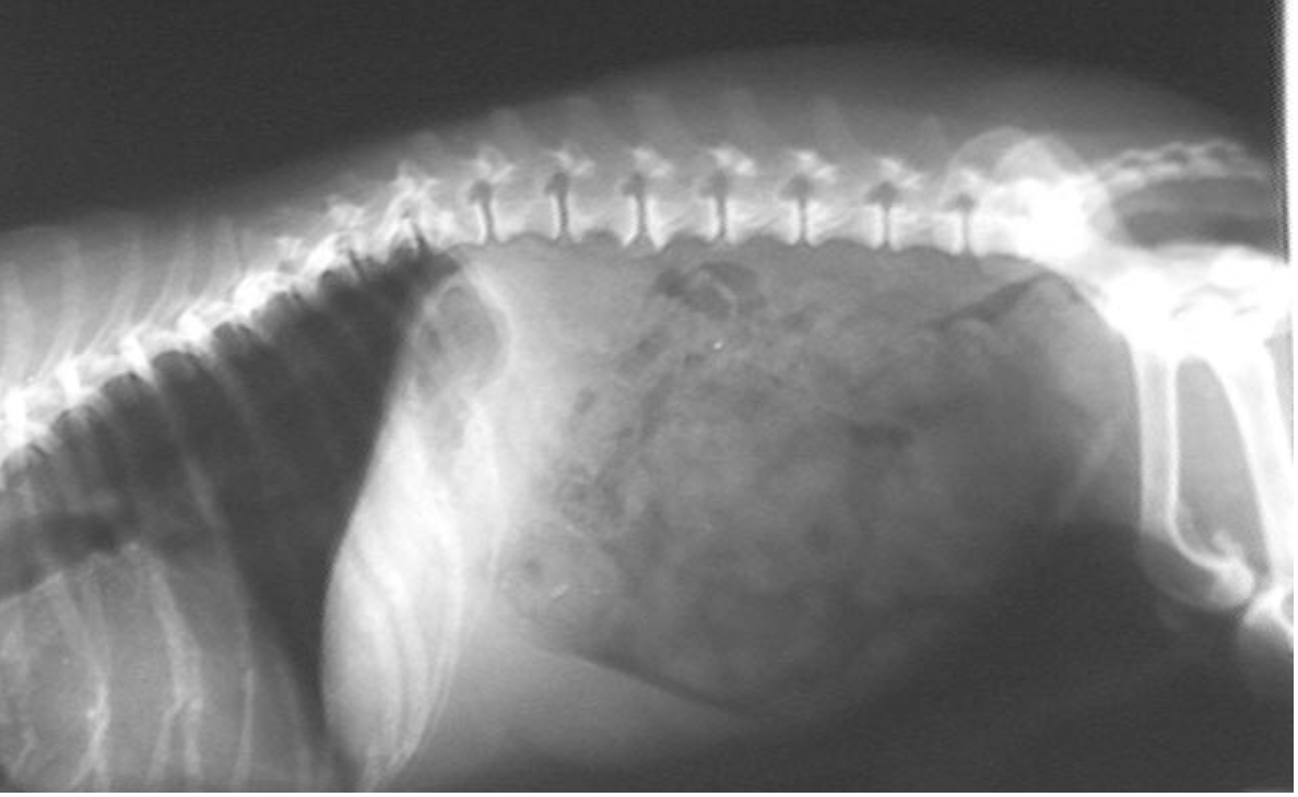
The term tissue density is used to describe the degree to which a patient or object absorbs incident x-rays. In the accompanying radiograph the bone tissue is denser than the adjacent soft tissue, but the differences in image tone should be described in terms of radiolucency and radiopacity. For example, in this radiograph, the soft tissues are more radiolucent than the bones.
Air and fat absorb relatively less radiation and are consequently radiolucent, so their images on the film will appear black and pale grey repectively. Bone and metal absorb much more X-radiation and are radiopaque, so their images are white. Most soft tissues in the body are composed mainly of water and appear as shades of grey. The radiopacity of most fluids (blood, urine, transudates, exudates, bile and cerebrospinal fluid) and non-mineralised non-adipose tissues (muscle, cartilage, tendons, ligaments, fascia and parenchymatous organs) is the same. Lead and other metals have high physical density and effective atomic number, which renders them extremely radiopaque.
3. Ultrasound course
Chapter 1 – Practical Physical Concepts and Artifacts
Image formation and other principles / Download – 51.7 MB
Propagation of ultrasound waves and interaction with tissues (see video 1)
Ultrasound beam and spatial resolution (see video 1)
Gain, time gain compensation, and other manual adjustments / Download – 167.1 MB
Vertebral mass invading the spinal canal / Download – 54.2 MB
4. Thermography
Dr Turner
Dr Marcella
Dr Hennemans
American Academy of Thermology’s Veterinary Guidelines
Heat is a cardinal sign of inflammation. Vasomotor tone and vasomotor capacitance plays a significant role in thermoregulation, clinical symptomatology and manifestations of systemic illness. In the Animal Kingdom the clinical manifestation of pain can be detrimental to survival. As such, changes in the previously mentioned vascular parameters may be the only clinical signs shown.
Infrared Thermal Imaging is the only non-invasive technology available to image and map circulatory changes associated with these disorders. It can play an important role in clinical diagnosis and enhance the clinical examination. But infrared imaging may also be valuable to document musculoskeletal stress caused by training as well as circulatory effects of therapeutic modalities. In addition, infrared imaging can be used as an aid in the regulation of the animal industry.
Other technologies such as Radiography, Ultrasonography, Scintigraphy, and MRI do not provide the same information offered by Medical Thermal imaging. The clinical application of Infrared Thermal may be instrumental in understanding the pathophysiology associated with veterinary disease and can lead to improved patient outcomes.
The mission and bylaws of the American Academy of Thermology support the incorporation of thermal imaging into veterinary clinical medicine. The AAT recognizes a current and ongoing need to promulgate continuing education in the science and methods of thermal imaging and the clinical application of heat asymmetry patterns obtained from thermal imaging among both veterinarians and thermal technologists.
PurposeVeterinary medicine is a unique branch of the health sciences that involves multiple species many of which are not domesticated. Regardless, any can be dangerous to the examiner. Furthermore, veterinary patients do not seek medical attention, rather the owner, rider, trainer, or caretaker seeks medical advice based on their observations. Thus, veterinary examinations must be very thorough with attention to basic clinical signs that provide insight to potential inflammatory conditions. Unfortunately, many veterinary patients can only be examined using anesthesia or sedation. The ability of infrared imaging to detect changes in the heat patterns of skin makes it an invaluable tool in the clinical assessment of veterinary patients with certain types of problems. The thermal examination can be performed from the cranium to the base of the spine, from the torso to the extremities, including the digits and may include the oral and abdominal cavities.
Common IndicationsThere are 4 common uses for infrared imaging in veterinary medicine (1-35)
As a diagnostic aid where changes in the thermal patterns of scanned areas suggest a regional or global diagnosis whereby anatomic imaging modalities can then be used to characterize the nature of the problem.
As a method to enhance clinical assessment of the veterinary patient to include:• Evaluation or follow-up of patients with known or suspected vasomotor instability.• Pre-procedure assessment to aid in the planning of interventional therapeutics or diagnostics• Follow-up to detect improvement, progression or spread of disease, which may reflect change in condition.• Evaluation of muscle and peripheral circulation• Evaluation of post-surgical swelling and wound healing• Evaluation of unexpected post-operative or post fracture pain.• Qualitative and quantitative assessment of the vasculature and blood flow to tissues• Evaluation of peripheral neuropathies.• Evaluation of inflammation associated with dental or periodontal disease• To determine if areas of palpable soreness are associated with changes in temperature• Monitoring of testicular temperature• Monitoring of extremities post cast application• Monitoring progression and appropriateness of exercise protocols through the post-injury rehabilitation process.
As a method to assess thermal, functional, ergonomic, musculoskeletal stress in animals during and after training, competition, daily routines, and travel & performance, including but not limited to:• Identification of the presence of subclinical inflammation to allow for appropriate intervention.• Assessment of hoof and shoe balance in horses.• Assessment of saddle & harness fit in horses.• Assessment of the effects of the rider on the horse’s back.• Evaluation of the ergonomic fitness of harnesses, thermal control/equipment vests and foot protection booties in performance and working animals.• Identification of the onset of hyperthermia.• Structural evaluation of thermal and functional conditions of animal facilities.
For regulatory medicine to determine welfare compliance in jumping horses and Tennessee Walking Horses (TWH) including but not limited to:• Assessment of limb temperature changes for limb sensitivity in show jumpers• Identification of abnormal cold on the distal limb of TWHs suggestive of foreign substance application• Assessment of thermal patterns on the palmar pastern of TWHs suggestive of abnormal scar formation• Assessment of thermal patterns of TWHs distal limbs consistent with application of “soring” agents
Contraindications and Limitations
Infrared thermal imaging shows only skin temperature and therefore is a reflection of the deeper tissues.Infrared imaging is highly sensitive to environmental factors and an understanding of these factors is imperative if infrared imaging is to be successful.• Infrared imaging is contraindicated if the thermal evaluator does not understand infrared radiation physics• Imaging is contraindicated if bilaterally symmetrical images cannot be evaluated.• Imaging is contraindicated if environmental factors cannot be controlled, including sunshine, ambient temperature, drafts, haircoat, topical moisture, topical liniments, andthe presence of bandages or blankets or articles of harness.• Imaging is contraindicated if the patient is uncooperative.
Guideline 1: Owner (Person Responsible) Communication and Veterinary Patient Preparation:
Communication- The examiner:1.1 Explains the medical necessity for performing infrared imaging to the Person Responsible (PR) for the Patient.1.2 Responds to questions and concerns from the PR about any aspect of the examination.1.3 Advises the PR about risk factors and the information hoped to be obtained by infrared imaging. Obtains informed consent either written or orally from the PR to proceed with infrared imaging.1.4 Refers specific diagnostic, treatment or prognosis questions to the Veterinarian.
Preparation:
1.5 The Patient should be as clean as possible and groomed to remove any debris from the body surface. Patient should not have contact with any object if that body part is being imaged. All leg wraps, bandages, blankets, or any other object having contact with the area of anatomy to be examined should be removed for a minimum of 20 minutes prior to the commencement of the Thermal Exam. Animals should not be touched or allowed to sit or lay down.1.6 Avoid placing any material of any kind on the patient’s skin, such as any skin lotions, liniments, fly spray, topical external parasite treatments, etc. The haircoat must be dry.1.7 The PR should declare the presence of any vasoactive topical or systemic substances to the examiner. Whenever possible steroids, sympathetic agonists and antagonists, vasoactive medications, opiates and transdermal patches should be avoided for 24 hours prior to testing. Exceptions should always be recorded in the record.1.8 Avoid any therapy or exposure that is applied to the skin, goes through the skin or may affect skin for 24 hours before imaging. The same is true for any electrodiagnostic technique that may affect skin. It should be noted within the record whenever exceptions are made and why.1.9 In the absence of extenuating circumstances, diagnostic studies using neurolytic blocks should be avoided for 3 days prior to testing.1.10 Controlled exercise such as riding, lunging or treadmill for horses, play, running or treadmill for dogs are useful dynamic examinations part of the thermographic evaluation but must be performed in a controlled manner. Intense exercise should be avoided in all animals for at least 2 hours prior to a resting examination.
Guideline 2: Patient Assessment
Patient assessment should be performed before infrared imaging.2.1 Obtain a complete, pertinent history by interview of the PR and/or review of the patient’s medical record. A pertinent history includes:a. Current medical status, especially regarding pain, lameness, and possible vascular issues.b. Presence of any signs or symptoms of vasomotor or other autonomic dysfunction.c. Relevant risk factors for injury, age, use, breed, and weightd. Symptoms of odontalgiae. Recent surgeryf. Pathology/Laboratory investigation values.g. Current medication or therapiesh. Results of other diagnostic Imaging modalities, radiographic, sonographic, scintigraphic, thermographic, computed tomography or magnetic resonance studiesi. Results of prior treatments
2.2 Veterinarians should complete a limited, focused, detailed or extensive physical examination, which includes assessment of all structures under study. The extent of the examination may be dependent on the tractability of the veterinary patient. Veterinary assistants should follow policy and procedure of the interpreting or attending veterinarian.
2.3 Compliance with Federal, State or other applicable regulatory rules and regulations should be maintained.
Guideline 3: Examination Guidelines
3.1 Infrared imaging measures and maps the degree and distribution of IR thermal emission. Skin temperature is largely under the control of the autonomic nervous system and inflammatory processes. Sagittal symmetry is expected throughout the body. Asymmetric IR emission of 1°C or greater can be indicative of sympathetic nervous system (SNS) dysfunction or other pathology.
Infrared evaluations do not test structure, but rather correlates to sympathetic nervous system physiology as well as local or systemic inflammation. Therefore, when structural injury is suspected additional radiographic imaging or diagnostic studies may still need to be performed.
Due to the complex nature and etiology of painful conditions associated with skin temperature asymmetry patterns, only those veterinarians trained in the proper techniques required to perform and interpret infrared imaging should do so. When present, the pattern of asymmetry discovered by infrared examination should guide the treating veterinarian in determining the source or generator of the abnormality. Both response to treatment and additional examination or testing may still be required to complete this task.
3.2 The following minimum specifications should be incorporated into the design of infrared hardware and software systems. These specifications are intended to speak to the design of modern infrared imaging equipment that is considered commonplace today. They are not intended in any way reflect on systems used in the past. While recognizing that individual circumstances will vary for the purposes of this document, lens FOV is 25 degrees, patient to camera distance 3-8 feet (as needed to allow the region of interest to fill approximately 75% of the image) and lens quality is satisfactory to the vast majority of observers. Camera temperature offset should be calibrated against the emissivity of a black body at 1.0 if needed for the examination being performed.
• Emissivity set to 0.98 (human skin) unless a different emissivity is both known and accepted for the animal and region of interest under study. The emissivity is a fractional representation of the amount of energy radiated from a material versus the energy that would come from a black body at the same temperature.• Camera detector spectral bandwidth: 8 to 14 microns (micrometers).• Preferred Absolute detector resolution of > 640 X 480 coupled with a suitable microbolometer and lens. Most modern medical imaging systems today utilize uncooled focal plane array detectors found in the 320 X 240 sensor range or higher. When systems with 320 X 240 sensors are coupled with a high-quality microbolometer, lens and compensatory software or firmware innovations they can approach the image quality, spatial resolution and spot measurement requirements found in 640 X 480 systems.• Min. measurable spot size is 2.1×2.0 mm (3×3 or 9 pixels) at 40 cm distance.• Spatial resolution quality at 8 feet (2.4 meters) equivalent to ≤ 2.6 mRad IFOV (Instantaneous Field of View) at 40 cm minimum focus.• Thermal sensitivity of < 50 mK NETD (Noise Equivalent Temperature Difference) @ 30 0C. • Ability to perform accurate quantitative differential temperature analysis with a precision of ≤ ± 0.05 0C (50mK). • Repeatability and precision of ≤ ±0.05 0C (50mK) detection of temperature difference. The repeatability of a differential measurement must be in the presence of +/- 3 NETD (6 sigma – 99.9% defect free mfg. standard).
• Thermal drift (caused by internal heating of equipment during normal operation or by changes in external ambient temperature) to be strictly controlled by calibration to a known temperature standard if necessary for the study under consideration.
• Maintenance of detector uniformity and correction via calibration to a known temperature standard. • Ability to render images in hi-resolution color and grayscale.
• High-resolution image visual display for interpretation.
• If video mode is used, it may incorporate real-time image focus and capture capability. While 10Hz, 20Hz, and 30Hz frame rates are capable of real-time imaging, faster capability is preferred (i.e.: 50Hz). For temperature analysis, radiometric video files are preferred.
• Precision Autofocus is recommended.
• Temperature range set to cover temperatures within the range of emissions (20-45 0C).
• Ability to archive images for future reference and image comparison at same patient positioning and distance from the camera.
• Software manipulation of the images should be maintained within strict parameters to ensure that the original qualities of the images are not compromised.
• Imaging software capable of identifying areas of temperature calculations and locations for reporting Appropriate infrared sympathetic skin response (SSR) instrumentation, which includes real-time display, electronic static image capture, storage, post-capture annotation or hard copy documentation capabilities, should be utilized.
3.3 All studies should be performed in an environment in which, to the extent possible, ambient temperature is controlled, free from drafts and where there is no exposure to infrared rays, such as incandescent lights or sunlight that may result in heating or reflective artifacts. The imaging room should be comfortably cool to allow for dissipation of superficial heat which may produce artifact from the skin. Ideally the ambient temperature range for IR imaging suite should be between 20° to 25°. However, as long as it is below 30º C and sweating is not induced, thermal imaging may be performed.
3.4 Ventilation systems should be designed to avoid direct airflow onto the patient. The patient should not be placed near or under any light fixture that itself emits heat. Standard fluorescent and/or LED lights are appropriate. Ideally the floor should be made of a non-reflective material.
3.5 Infrared studies can usually be accomplished with one set of images, however, post exercise examination or saddle test examinations require more than one set of images. Images taken in these serial studies should have accompanying time stamps for clarity.
3.6 A standard exam protocol for each segment evaluated should be used. Each point of focus should include dorsal, palmar/plantar, medial, and/or lateral views, as required. Contralateral and dorsal views should be equidistant and fill the image screen. When possible, it is recommended that the contralateral extremity images should be captured in the same image as the extremity under examination. Obtaining additional images may be required for patients with specific, unique circumstances.
3.7 Neuro-musculoskeletal (NMSK) studies that wish to highlight vasomotor mapping and that are prepared for interpretation without post-acquisition radiometric image manipulation typically employ palettes of no less than ten colors and are formatted at 1°C per color. Many have found it beneficial to use a temperature span of more than 10°C (the 1°C per color format, however, is retained). The intent of using a broader temperature span is to ensure that no relevant radiometric image information is lost at the extremes of temperature maxima or minima across a wide range of regions of interest.
While vasomotor mapping may be more readily visible with a 1°C per color palette, gradient palettes that span less than 10°C are also commonly employed in NMSK studies that have a limited focus or region of interest and where visualization of vasomotor maps may not be necessary for that study’s intended use. Nonetheless it is the interpreting thermologist’s responsibility to make sure that the absence of a vasomotor map is not clinically relevant for each study performed where the same is omitted.
The interpreting thermologist must also ensure that the range of temperature maxima and minima utilized does not exclude pertinent radiometric data. Individual protocols for acquisition that do not exclude relevant findings should be established. If a small temperature span is employed the interpreting physician should explain why it was required.
3.8 The patient’s physical and demeanor is assessed and monitored during the examination, with modifications made to image acquisition as necessary. Also, findings are analyzed throughout the course of the examination so that the veterinarian is provided sufficient data to direct patient management and render a diagnostic impression.
3.9 Appropriate infrared instrumentation, which includes real time display, electronic static image capture, storage, post capture annotation, or hard copy documentation should be utilized. It is further recommended that static image files be available for viewing and storage, either as radiometric or JPEG images stored in a unique folder for each animal patient, or in Digital Imaging and Communications in Medicine (DICOM) format for Picture Archiving and Communication System (PACS) distribution.
3.10 Evaluate the patient’s physical and mental status prior to discharge. Additional discharge instructions to the PR may include recommendation to schedule follow up appointment with the attending veterinarian, and to resume all medication medical treatment that may have been discontinued prior to the infrared study.
Guideline 4: Review of the Infrared Thermography Examination
4.1 The data acquired during the extremity and spinal infrared examination should be reviewed to ensure that a complete and comprehensive evaluation has been performed and documented. Any exceptions to the routine examination protocol (i.e., study omissions or revisions) should be noted and reasons given.
4.2 The examiner should record all technical findings required to complete the final interpretation so that the measurements can be classified according to the standard laboratory diagnostic criteria.
4.3 The examiner should complete the required documentation of the study in a timely manner.
4.4 The examiner should alert the medical director or other responsible veterinarian when immediate medical attention is indicated, based on the infrared examination findings.
Guideline 5: Presentation of Exam Findings
5.1 The examiner must provide preliminary results as provided for by internal policy based on examination findings.
5.2 The examiner must present the record of diagnostic images and when applicable, explanations for sub-optimal examination findings to the interpreting veterinarian for use in diagnosis and archival purposes.
Guideline 6: Preparation and Storage of Exam Findings
6.1 Images should be presented to the interpreting veterinarian for use in analysis and archival purposes. Radiometric images in either radiometric image format or radiometric image convertible format such as JPEG or DICOM are acceptable. A color-to-temperature Thermal Scale must accompany each image.
6.2 The imaging clinic should adhere to all established federal and state regulations. Archiving of image data and the analysis/report are to be maintained for no less than seven years.
Guideline 7: Exam Time Recommendations
High quality and accurate results are fundamental elements of the infrared study. A combination of direct and indirect exam components is the foundation for maximizing exam quality and accuracy.
7.1 Indirect exam components include pre-exam procedures: a) obtaining previous exam data, completing pre-exam paperwork, b) exam room and equipment preparation and c) patient assessment, history, and positioning.
7.2 Post exam procedures include: a) clean up consisting of compiling, processing, and reviewing data for preliminary and/or formal interpretation , b) Communication with the Person Responsible (PR) c) examination charge and billing activities where appropriate. Recommended time: 30-60 minutes.
7.3 Direct exam components include: a) equipment optimization, b) patient positioning throughout the exam, c) the actual hands-on examination process. Recommended time: 20-60 minutes.
Guideline 8: Reporting
8.1 A medical record report should be prepared within 24 hours of the study. As part of the imaging protocol, the thermographer should consider sending each PR a summary report within 30 days of the thermographic examination.
8.2 Report layout: The body of the Infrared Veterinary Thermographic report should clearly state that procedures that follow a peer reviewed, internationally accepted guideline was utilized. The set of images obtained for study should be documented. If a standard protocol for reading images is used then this should be stated as well.
Thermographic Findings should be documented and any abnormalities noted. Findings include asymmetry of > 1 degree Centigrade in > 25% of the surface area of any individual region of interest and localized hot or cold spots.
Thermographic impressions include classification according to an accepted naming system or summarization of the thermographic findings. When recognized patterns (thermal signatures) are seen, the thermographic impressions may include the description of that pattern (for example: a back thermographic pattern consistent with overriding vertebral spinous processes) however care should be taken not to make any statements about clinical diagnosis in this section of the report. That is these patterns have been associated with particular disease but the pattern does not prove the disease.
Clinical Impressions are not to be included in the Thermographic Findings paragraph but rather in a separately identifiable paragraph that speaks to the generator or etiology of those findings. Any discussion that is clinically relevant should be reserved for this paragraph.
Guideline 9: Continuing Professional Education
Certification is considered the standard of practice for infrared technology. It indicates an individual’s competence to perform medical technology at the entry level. After achieving certification, all Registered Infrared SSR Technologists are expected to keep current with:
9.1 Advances in diagnosis and treatment of pain syndromes with and without sympathetic nervous system dysfunction (vasomotor instability).
9.2 Changes in infrared examination protocols or published laboratory diagnostic criteria.
9.3 Advances in infrared technology used for veterinary examinations.
9.4 Advances in other technology used for infrared examinations.
Guideline 10: Emerging Technologies
10.1 Technology is constantly being introduced that can challenge existing guidelines or that do not necessarily conform to currently accepted practices. These technologies can span the entire spectrum of sophistication and therefore require different adaptive responses. On one end of the spectrum there are innovations based upon generally accepted medical scientific methodology that have gained regulatory acceptance and on the other end there are technologies that are intended for personal use only or that have applications in non-medical fields but have not been accepted as suitable for medical practice.
10.2 General industrial or personal thermal imaging cameras that do not meet the specification guidelines contained herein are not intended for use in Medical Thermology.
10.3 Technologies not otherwise covered in these Guidelines that employ methodologies, hardware, or protocols that have gained Federal Regulatory approval for Medical Thermology may become available however over time. In cases where these technologies are employed the body of the report should document which deviations occurred and why, and other components of the Guideline should still be followed.
References
Turner TA, Fessler JF, Lamp M, Pearce JA, Geddes LA: Thermographic evaluation of horses with podotrochlosis. Am J Vet Res 44(4):535-539, 1983.2. Loughin CA, Marino DJ: Evaluation of thermographic imaging of the limbs of healthy dogs. American Journal of Veterinary Research, 68(10): 1064-1069, 2007.3. Ringer SK, Lischer CJ, Ueltschi G: Assessment of scintigraphic and thermographic changes after focused extracorporeal shock wave therapy on the origin of the suspensory ligament and the fourth metatarsal bone in horses without lameness American Journal of Veterinary Research , 66(10): 1836-1842, 2005.4. Purohit RC, McCoy MD. Thermography in the diagnosis of inflammatory processes in the horse. Am J Vet Res; 41:1167–1174, 1980.5. Vaden MF, Purohit RC, McCoy MD, Vaughan JT. Thermography: a technique for subclinical diagnosis of osteoarthritis. Am J Vet Res; 41:1175–1179, 19806. Simon EL, Gaughan EM, Epp T, Spire M: Influence of exercise on thermographically determined surface temperatures of thoracic and pelvic limbs in horses, J Am Vet Med Assoc, 229:12, 1940-1944, 20067. Von Schweinitz: Thermographic diagnostics in equine back pain. Vet Clin North Am Equine Pract. Apr, 15 (1):161-77, 19998. Denoix JM: Diagnostic techniques for identification and documentation of tendon and ligament injuries. Vet Clin North Am Equine Pract. Aug ,10 (2):365-407, 19949. Turner TA: Diagnostic thermography,Vet Clin N.A.: Equine Pract. 17(1): 200110. Turner TA: Thermography as an aid to the clinical lameness evaluation, Vet Clin of N.A.: Eq Prac, 7(2): 311-338, 199111. Turner TA: Hindlimb muscle strain as a cause of lameness in horses. 35th Annu Meeting of Am Assoc of Equine Practnr, 1989: 281-290.12. Turner TA, Wolfsdorf K, Jourdenais J: Effects of heat, cold, biomagnets and ultrasound on skin circulation in the horse. 37th Annu Meeting of Am Assoc of Equine Practnr, 1991: 249-25713. Waldsmith JK. Real-time thermography: a diagnostic tool for the equine practitioner. 38th Annu Conv Am Assoc Equine Pract 1992; 38:455–466.14. Turner TA: Use of thermography in lameness evaluation.44th Annu Meeting Am Assoc Eq Practnr, 1998: 224-226.15. Tomlinson JT, Sage AM, Turner TA: Ultrasonographic examination of the normal and diseased equine pelvis. 46th Annual Meeting Am Assoc Eq Practnr, 2000: 375-377.16. Turner TA: Pansch J, Wilson JH: Thermographic assessment of racing Thoroughbreds. 47th Annual Meeting Am Assoc Eq Practnr, 2001: 344-346.17. Turner TA: Back problems in horses. 49th Annual Meeting Am Assoc Eq Practnr, 2003: 71-74.18. Turner TA, Waldsmith JK, Wilson JH: How to assess saddle fit in horses. 50th Annual Meeting Am Assoc Eq Practnr, 2004: 196-201.19. Mogg KC, Pollitt CC. Hoof and distal limb surface temperature in the normal pony under constant and changing ambient temperatures. Equine Vet J 1992; 24:134–13920. Marr CM. Microwave thermography: a non-invasive technique for investigation of injury of the superficial digital flexor tendon in the horse. Equine Vet J 1992; 24:269–27321. van Hoogmoed L, Snyder JR, Allen AK, Waldsmith JD. Use of infrared thermography to detect performance-enhancing techniques in horses. Equine Vet Educ 2000; 12:102–107.22. Tunley BV, Henson FM: Reliability and repeatability of thermographic examination and the normal thermographic image of the thoracolumbar region in the horse. Equine Vet J. 2004 May;36(4):306-12.23. Holmes LC, Gaughan EM, Gorondy DA, Hogge S, Spire MF: The effect of perineural anesthesia on infrared thermographic images of the forelimb digits of normal horses. Can Vet J. 44(5): 392–396, 2003.24. Cockcroft PD, Henson FM, Parker C. Thermography of a septic metatarsophalangeal joint in a heifer. Vet Rec. 146:258–260, 2000.25. Eddy AL, van Hoogmoed LM, Snyder JR. The role of thermography in the management of equine lameness. Vet J. 162:172–181, 2001.26. Turner TA. Alternate methods of soft tissue imaging. Dubai Int Equine Symp: 165–176, 1996.27. Waldsmith JK, Oltmann JI. Thermography: subclinical inflammation, diagnosis, rehabilitation, and athletic evaluation. J Equine Vet Sci.14:8–10, 1994.28. Turner TA, Scoggins RD: Thermographic detection of gingering in horses. J Eq Vet Sci, 5(1):8-10, 198529. Turner TA, Fessler JF, Purohit R: Thermography: A review in equine medicine. Comp Cont Ed, 8(11):855-862, 1986.30. Turner TA: Thermography as an aid in the localization of upper hindlimb lameness. Pferdeheilkunde, 12(4), 632-634, 1996.31. Turner TA: Uses and limitations of thermography. Pferdeheilkunde, 12(4), 684-685, 1996.32. Verna M, Turner TA, Anderson K: Scintigraphic, radiographic, and thermographic appearance of the metacarpal and metatarsal regions of adult healthy horses treated with non-focused extracorporeal shockwave therapy-a pilot study. Vet Therapeutics, 6(3): 268-276, 200533. Purohit RC, Pascoe DD, Turner TA: Use of thermography in veterinary medicine, in Bronzino JD (ed): The Biomedical Engineering Handbook, 3rd Edition, CRC, Taylor and Francis Publication, pp 35,1-8, 2006.34. Purohit RC: Use of thermography in veterinary medicine, in Cohen JM and Lee MHM (eds): Rehabilitation Medicine and Thermography, Impress Publication, pp135-147, 2008.35. Westermann S, Heinz H. F. Buchner, Johannes P. Schramel, et al.: Effects of infrared camera angle and distance on measurement and reproducibility of thermographically determined temperatures of the distolateral aspects of the forelimbs in horses. Journal of the American Veterinary Medical Association, Vol. 242 (3), 388-395, 2013.36. Levet A, Martens L, Devisscher L, et al: Distal limb cast sores in horses: Risk factors and early detection using thermography. Equine Vet J, Volume 41 (1), 18–23, 2009.37. Westermann S, Stanek C, Schramel JP, et al: The effect of airflow on thermographically determined temperature of the distal forelimb of the horse. Equine Vet J, doi: 10.1111/evj.12019 : 2013